After flooding caused by the breach of the Inbanuma levee, the fire department and media reported that there are about 30 combiner boxes, and that a submerged box may have shorted when the water level dropped and exposed it. There were repeated ignition and natural extinguishing, many explosion sounds, and because of the risk of electric shock and the limited fire spread, no firefighting was carried out, and there were no injuries.
According to public information, the facility is said to be the "Narita City Otake solar power plant," leased by a company related to the Hiroshima Construction Group, and was installed in or after 2015. The forensic result for the cause of the fire, the PCS manufacturer, output, junction box model, and monitoring granularity have not been disclosed. Therefore, rather than evaluating individual equipment, this discussion considers the facility configuration that can be confirmed from reports and the issues common to centralized solar PV systems.
There are three major options for recovery after flooding. Return to the same junction boxes and central inverter, keep the centralized configuration but replace only the PCS with a new unit, or move to string PCS and, if necessary, MLPE to redesign the collection and maintenance units. The differences are not limited to equipment price. The range affected by the next failure, the level of detail at which the cause can be identified, and the time required for recovery all change.
Other language versions: Japanese / English / Simplified Chinese / Playlist / Video list on site
What short-circuited was the junction box, not the panel
The likely source of the fire is the combiner box that collects generated power. The fire department explained that a submerged box shorted when it became exposed. This is not a confirmed forensic determination.
The panels continue to output DC while there is sunlight, and at night the generation current drops to almost nothing. Compared with full submersion, exposure and partial exposure make arcs more likely. When sunlight hits a wet box, voltage continues to be applied to locations where insulation does not recover.
During flooding, spraying water or approaching in daylight puts electric shock first. If the fire spread is small, there is no scaffolding, and DC is still live, it is reasonable to wait until the water recedes before cutting it off. If cutting it off, night is suitable. This is not a recommendation to leave it alone. If the fire spreads to buildings or oil, people need to enter, or DC can already be isolated, the procedure changes.
Why are junction boxes scattered within the array?
A configuration with many junction boxes across the array is often seen in centralized systems, also called central or multi-central, where DC is combined on the panel side and sent to a small number of PCS units. Strings are paralleled in boxes and carried to the PCS with thick DC cables, so the boxes are scattered between rows. The reported arrangement of about 30 locations overlaps with this typical configuration. However, because a single-line diagram has not been disclosed, this does not confirm the system used at the power plant in question.
One box collects many strings. If insulation fails, the collected DC and the long wiring from the box to the PCS are more likely to be affected. The number of shutdown points, approach points, and isolation units increases by the number of boxes, not just one point in the PCS room. The fact that it was installed in 2015 or later does not determine remaining life. It only means the inverter, DC cables, and combiner boxes are entering replacement age around the same time.
Reasons to replace a central inverter even without a fire
Replacing a central inverter is not something to consider only because of this fire. In a centralized system, one or a few units handle most of the power generation, so even if one unit fails, the shutdown is not limited to just a few strings. In another case published by I-S3, a failure of a single central inverter stopped the entire power plant, and in addition to the cost of the manufacturer's investigation, there was lost revenue from selling power while waiting for parts (record of repair costs).
Large early-FIT units had the advantage of reducing the number of installed units and lowering initial costs. TMEIC, ABB, and Hitachi Industrial Equipment Systems are representative examples that explained the centralized market at the time. This does not indicate the equipment manufacturer at Narita. As the market shrinks, the number of technicians who can respond and the supply of boards and power units becomes limited, making the operation of "continuing to use the system while repairing it even if it fails" difficult in itself.
In another consultation with I-S3, a repair estimate of 6.4 million yen was presented for a 630 kW-class central inverter that had been in operation for about 12 years. The company therefore compares, under the same conditions, the option of repairing the existing unit and the option of upgrading to a string-type system (consultation on 6.4 million yen). This is a separate case from the Narita facility, but it shows the need to judge not only repair costs, but also the next failure and the maintenance structure.
Centralized systems also have mismatch between panels. This is because the weakest panel in a string suppresses the current of the entire string due to shading, dirt, or degradation. Against the condition where one shaded panel causes the entire string to drop, module-level optimization reduces the range affected even to healthy panels. The background to centralized systems becoming less likely to be chosen for new installations includes efficiency, parts supply, and power generation losses during failures, as well as difficulty approaching the disconnect point, coarse monitoring, and recovery methods that wait for manufacturer technicians.
In I-S3 repowering, construction on the new equipment proceeds while the existing equipment remains in operation, and the system is stopped only at the time of switchover. The approximate downtime is 1 to 2 days for low-voltage systems and 3 to 7 days for high-voltage systems, but it varies depending on the wiring and equipment configuration (organizing downtime). In another case, the results were 2 days of downtime and an 18% increase in first-year generation for a 50 kW-class low-voltage system, and 5 days of downtime and a 14% increase in first-year generation for a 500 kW-class high-voltage system, including replacement of the connection box and distribution board. These are results from individual cases and do not guarantee the same effect at the current power plant.
Why power generation does not recover even after inspection
What works first is the range affected by a failure. In a centralized system, while it is still unclear whether the fault is in the PCS, the combiner box, or which string, a large block of generation stops, and the investigation also begins with that block stopped. In string PCS systems, the stopped range tends to be limited to one unit or a few strings. With MLPE, publicly available comparisons show that generation can continue for units other than the faulty optimizer. Ground faults in DC, submerged connectors, and broken conductors still require cable investigation even if the PCS is made smaller.
Another advantage is that data can be used to narrow down the investigation targets. Monitoring in centralized systems is centered on PCS output and total string current, and even if power generation drops, it may not be clear whether the cause is shading, disconnection, or dirt until it is checked on site. With string PCS, the strings to be checked can be narrowed down by comparing adjacent strings. Furthermore, if MLPE and PLM are introduced, current and voltage at the panel level can be checked. However, simply replacing with string PCS does not mean that a single panel can be identified.
In I-S3 failure analysis, PLM and on-site IV characteristic measurements are combined to distinguish between optimizer defects and poor wiring contact (sorting out the cause of reduced generation). There are also operational examples in which alert thresholds and seasonal correction reduced unnecessary site visits (remote PLM triage). Even with detailed monitoring data, it cannot be used for maintenance unless appropriate thresholds are set, seasonal variation is corrected for, and it is decided who checks which string.
The recovery method also affects time and cost. In the case of a large unit failure, investigation by manufacturer technicians, quotation, and parts procurement are required in sequence, and electricity sales losses continue during that time. In the case introduced earlier, costs on the order of several hundred thousand yen arose from the stage of requesting an investigation. On the other hand, if the faulty location can be identified down to the PCS or optimizer and replacement parts are secured, power generation can be restored by replacing the target unit. The actual replacement time depends on site conditions and inventory, but the finer the data granularity and the more the replacement unit matches it, the faster recovery becomes. If the cause cannot be identified, investigation is necessary even if the equipment is small.
Periodic inspections are important work that reliably performs tightening, insulation checks, visual inspection, cleaning, and measurement. However, completing inspection records is not the same as identifying and improving the cause of reduced power generation. If it is not clear which module is dragging down the entire string, the same inspection will simply be repeated the following year and power generation will not recover. Even if more inspection items are added while keeping the centralized configuration, the problem remains that the cause cannot be narrowed down because information is still concentrated in the junction boxes and large PCS units.
What should be advanced at the same time as decentralization is monitoring at the string or module level, prioritization of alerts, identification of targets before a visit, and unit replacement after identification. Without this operation, decentralization may only increase the number of boxes to inspect. For future O&M, it is necessary to connect inspections to data-driven repair and replacement, and then to verification of generation after the work (SolarEdge O&M).
With a new central unit, the issues of not being able to shut it off and waiting for repairs remain
The issue newly revealed by this flooding is that DC collection points are scattered within the array while still carrying voltage under sunlight. The approximately 30 junction boxes become exposed or semi-exposed as the water level falls, creating places where arcs can occur. The places that must be approached for shutdown also exist in the number of junction boxes. If the fire spread is small, access is not possible, and the DC is still live, it should not be forcibly shut down until scaffolding can be secured. On the other hand, the ability to shut down at low irradiance and the decision to leave a design that still requires people to go to each location in the next flood are separate issues and should be considered separately.
A distributed system separates conversion points closer to the array and reduces long high-voltage DC runs and large combiner boxes. The impact tends to stay limited to one unit or a few strings, and monitoring is also at the string level. Small collection circuits and connectors remain. Even in a distributed system, a submerged PCS, connectors, and arcing at broken conductors can still occur.
If only the PCS is replaced with a new unit while keeping the centralized configuration, the aging converter and parts supply issues can be temporarily eased. However, the long DC collection lines, numerous junction boxes, monitoring centered on aggregate values, and recovery methods that wait for manufacturer repairs remain. If safety after a fire and future maintainability are considered, it is necessary to review not only the PCS but also the collection and monitoring units.
| Item | A Return to the same configuration | B Update only the PCS | C string (MLPE if needed) |
|---|---|---|---|
| Length of the DC collection line | Long collection lines remain | Long collection lines remain | Reduce long high-voltage DC lines |
| Scope that stops in the event of a failure | Large | Even new ones are large | From one unit to several strings |
| Where people shut it off during flooding | Only as many as the combiner boxes | Only as many as the combiner boxes | Large systems decrease. Small-scale collection remains |
| Parts supply | Depends on the current model | Mitigated while new | Current strings or MLPE |
| Mismatch | The weakest one pulls the string | Remains centralized | Mitigate with strings. MLPE for panels |
| A unit that can be identified | Depends on the total | Granularity depends on the design | String. If PLM, panel |
| How to restore | Inspection and repair | Manufacturer repair again | Replace if it can be identified |
| Whether inspection leads to power generation | Often ends with records only | The places to check remain centralized | When raised to monitoring and replacement |
After flooding, compare the restore option and the replace option with the same estimate
After flooding, drying, insulation measurement, and checking the junction boxes and cables are often unavoidable. The period when the power plant is stopped, or must be stopped for insulation checks, is also a time when repowering, which would normally be postponed because of lost electricity sales, can be compared within the same scaffolding, outage, and cable work as the recovery work. Rather than using the disaster as an excuse to renew the system, it is important to compare the cost of returning to the original configuration with the cost of changing the collection and maintenance configuration under the same estimate conditions.
Repowering is not a simple replacement with a new inverter. It is a redesign that simultaneously determines the string configuration, cable diameter, open-circuit points, remote shutdown, assumed flood height, work flow, monitoring granularity, and spare units. If DC cables are also replaced in flood recovery, whether the collection method can be reviewed within the same work affects the cost. Even for projects with a short remaining FIT or FIP period, if the lost revenue from waiting for repairs and the future risk of parts supply are large, upgrading to a decentralized system becomes a candidate for consideration. The overall picture of the decision is organized on the repowering page.
I-S3 Co., Ltd. handles this design, construction, and operation from local electrical and civil engineering work. Its locations are in Annaka City and Takasaki City, Gunma Prefecture. It handles EPC, O&M, repowering, self-consumption, and EV charging integration as on-site work, and looks at equipment through configuration and data rather than personal connections. Separate from completing inspections, it decides where to go through monitoring and also looks at generation after replacement. Self-consumption, repowering, and O&M are supported nationwide. Downtime proceeds while keeping the existing system running, and it is stopped only at the time of switching over. The number of days varies depending on changes to wiring and monitoring, so no commitment is made.
10 items to check before restoring
- Number of junction boxes and their positions within the array.
- DC voltage and the length from the box to the PCS.
- Number of PCS units, spares, and outlook for parts supply.
- Flood assumption height and the difference from the water level this time.
- Remaining years of FIT or FIP.
- Can the DC cable be renewed at the same time this time?
- Is monitoring by total, by string, or by panel?
- In the event of a failure, do we wait for the manufacturer's investigation or replace it with a spare?
- Does the previous inspection include any measure that changes next year's power generation?
- After decentralization, is there someone who decides alert priority and which row to go to?
Floodwater level and equipment height
In news footage, as the water receded, the solar panels were above the water surface, but the junction boxes fixed at a lower position than the panels remained submerged (Nikkei BP Mega Solar Business, September 30, 2026). Once sunlight hits the panels, power generation begins, and DC flows into the junction boxes in the water. The fire occurred two days after the levee breach (September 22), overlapping with the time when the water level began to fall.
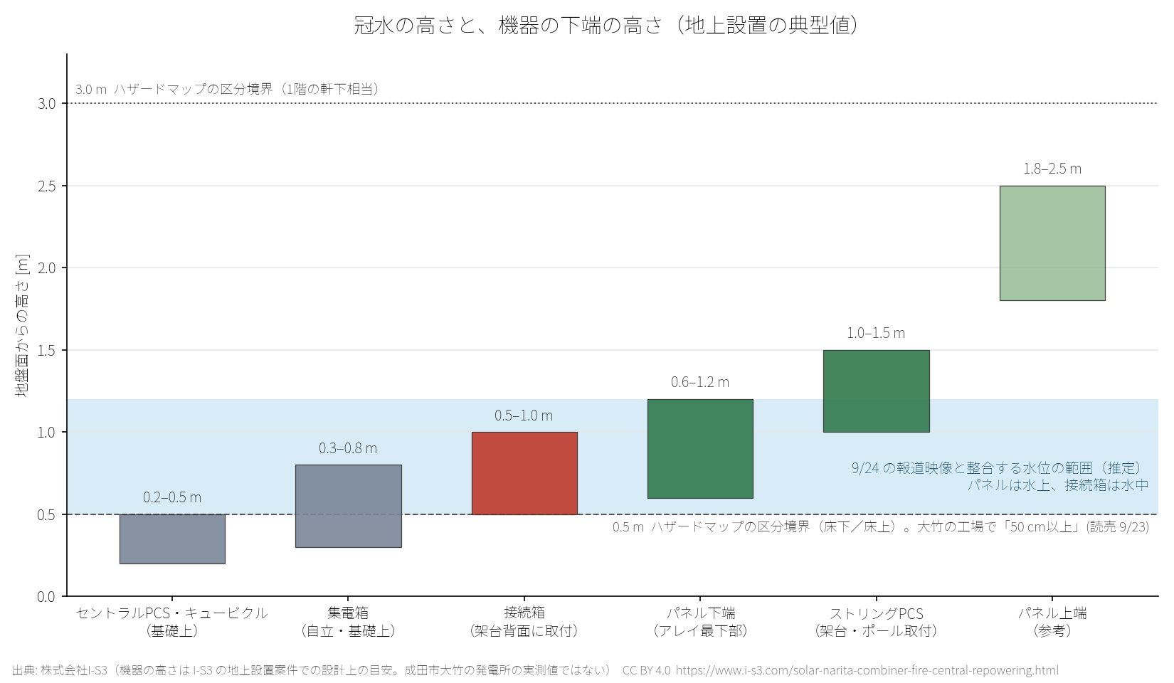
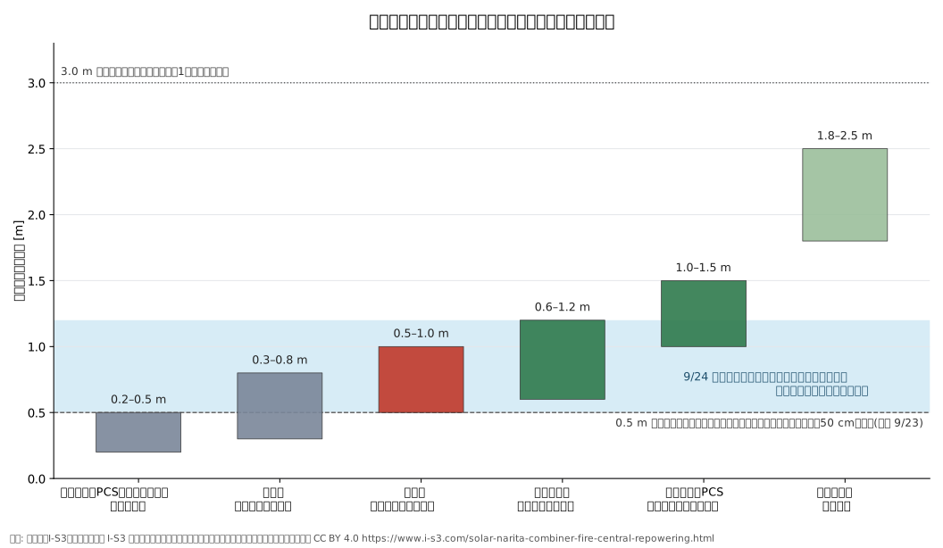
There are three points to note. First, in centralized systems where junction boxes and collection boxes are placed on the rear side of the mounting structure or on the foundation, the lower edge is typically about 0.5 to 1.0 m above ground, so once the flood depth reaches the floor-inundation category (0.5 m or more), they are submerged. Because they are lower than the lower edge of the panels, there is inevitably a period during the receding water phase when "the panels are generating power while the boxes are underwater." Second, in configurations where string PCS are mounted high on the mounting structure or on poles, the lower edge often exceeds 1.0 m, expanding the range in which they can avoid submersion at the same water level. However, small collection devices and connectors remain. Third, in locations where the hazard map assumes an inundation depth exceeding 3.0 m, no equipment can escape by height alone, and the design focus must be on being able to cut DC remotely and on deciding restoration procedures in advance.
A submerged box does not regain insulation even after it dries
In a submersion test conducted by the Japan Photovoltaic Energy Association (JPEA) under commission from NEDO, insulation resistance was tracked after submerging the junction box and PCS in water. The junction box dropped immediately after being lifted out of the water to 0.01 to 0.1 MΩ, and even after 7 days it remained at 0.2 to 2.6 MΩ depending on the type; even after washing and drying one month later, it did not return to the pre-submersion level (several hundred to over 4,000 MΩ). The PCS recovered to the 500 MΩ range after 7 days, but remained lower than before submersion. In PCS units with strings still connected, smoke, sparks, and scorching were confirmed between terminals on the day of submersion and the following day. The report states that submerged junction boxes and PCS should preferably be replaced, and that the modules should be disconnected as soon as possible (JPEA / NEDO "Report on Submersion Tests of Photovoltaic Power Generation Systems (Excerpt)" 2019-08-30).
| Equipment | Before inundation | Immediately after recovery | 4 days later | 7 days later | 1 month later Cleaning and drying |
|---|---|---|---|---|---|
| Combiner box (steel plate, diode) | 817 | 0.012 | 0.686 | 419 | 32.8 |
| Combiner box (steel plate, fuse) | >4000 | 0.004 | 0.01 | 0.18 | 24.2 |
| Combiner box (resin, fuse) | >4000 | 0.1 | 0.029 | 2.16 | 46.2 |
| PCS | >2000 | 0.01 | 0.319 | 659 | — |
If we overlay this with the Narita timeline, the phase two days after the levee breach, when the water level fell and the junction boxes became exposed or partially exposed, is close to the experimental condition in which smoke and sparks were observed: "from the day of submersion to the next day, with the string still connected." The question for restoration is not whether a dried box can be used again, but at what unit level submerged DC equipment should be replaced, and whether the configuration can be made so that DC can be cut off without people approaching it during the next flood.
Inspection and power restoration checklist after the water recedes
We have compiled a single page that checks everything in order, from before approaching to monitoring after reconnection. The printable PDF (one A4 page) is under CC BY 4.0 and can be freely used at the site and in the office. Laws, safety regulations, and manufacturer instructions take priority. On September 25, 2026, the Ministry of Economy, Trade and Industry issued guidance asking installers to prevent electric shock and short-circuit fires caused by flooded solar power generation equipment (Environmental Business Online, September 29, Ministry of Economy, Trade and Industry: warnings during natural disasters). Please also refer to JPEA's procedures and points to note for inspections and removal during flooding.
A. Before approaching (while flooded until the water recedes)
- Do not approach equipment that is submerged. Put up no-entry signs and ropes. Also inform nearby residents
- For 50 kW or more, contact the appointed chief electrical engineer; for under 50 kW, contact the sales and installation contractor. Inform the power company of the situation
- Check whether damage or fire falls under the accident reporting requirements of the Electricity Business Act reporting rules, and if applicable, report it to the Industrial Safety and Inspection Department within 24 hours
- First report to the insurance company. Preserve photos, videos, and monitoring screens with timestamps
- Do not isolate until scaffolding or a stable work platform is secured. Limit work to dusk to low-irradiance hours
B. Isolation (separate the power generation side and the grid side)
- Grid side: open the breaker at the point of interconnection and the AC side of the PCS
- DC side: open in order the PCS DC switch, then the junction box switches and fuses, then the string connectors
- Separate the strings from submerged junction boxes and PCS as quickly as possible (in submersion experiments, smoke and sparks occurred between P and N on the same day to the next day)
- Insulated gloves, insulated boots, and insulated tools. Use a DC-compatible voltage tester to confirm no voltage before touching
C. Recordkeeping (for insurance, cause analysis, and redesign)
- Measure the waterline trace for each piece of equipment (difference from the lower edge of the junction box, collector box, PCS, and cubicle)
- Enter the locations of mud, debris, rack deformation, and cable断線 on the single-line diagram and layout drawing
- Export and save monitoring data (shutdown time, ground fault alarm, string current)
D. Drying, cleaning, and measurement
- Remove mud, wash with fresh water, and dry. Open the enclosure and check that no water or mud remains inside
- Insulation resistance: array (P-G / N-G), junction box, DC cable, PCS, and AC side. As a guideline, JIS C 62446-1 specifies 1 MΩ or more for system voltages above 120 V (test voltage 500 / 1000 V). For low-voltage AC circuits, the lower limits are 0.1 / 0.2 / 0.4 MΩ under Article 14 of the Interpretation of the Electricity Business Act
- Ground resistance and continuity of grounding conductors
- Compare the open-circuit voltage and short-circuit current (or IV characteristics) of each string with adjacent strings
E. Equipment assessment (repair or replace)
- As a rule, replace submerged junction boxes, PCS, fuses, SPD, switches, and terminal blocks. Even after washing and drying, insulation does not return to the pre-submersion state (NEDO/JPEA submersion experiment)
- Replace submerged connectors. Cut back or replace cables at the flooded ends
- Panels: replace if there is glass breakage, water ingress into the junction box, or insulation failure. If there is no problem, wash and use
- Compare returning to the same configuration / replacing only the PCS / changing the collection method as well under the same estimate conditions (comparison table in the article)
F. Restoration of power and reconnection
- Obtain confirmation from the chief electrical engineer and keep records in accordance with the safety regulations
- Reconnect after contacting the power company. Turn on the AC side first, then energize the DC side gradually string by string
- Monitor on site on the first day. Check for ground fault alarms, PCS abnormalities, and variations in string current
- For one week, compare string-level generation with adjacent strings and inspect on site any strings that still differ
G. Preparing for the next flood
- Record the assumed flood depth from the flood hazard map alongside the lower edge height of each piece of equipment
- Consider whether the lower edges of the junction box, collector box, and PCS can be raised above the assumed flood depth, and whether remote shutdown can be added
- Put the contact points and procedures for flooding on one sheet and keep it on site and in the office
Timeline of weather, government, operator, and media reports
We list, with sources, the period from Typhoon No. 25 on September 19, 2026 through the emergency restoration of the embankment in early October. The operator's announcement (Senario Hiroshima GHD) was issued twice, in the first report on September 24 and an update on September 29, and no conclusive forensic determination of the cause of the fire has been made public as of this article's update. The same content and source URLs are available in the CSV.
| Date and time | Subject | events | Source |
|---|---|---|---|
| 2026-09-19〜22 | Weather | Typhoon No. 25. Narita City's 48-hour rainfall was approximately 327 mm (until 05:50 on 9/22, Chiba Prefecture Disaster Response Headquarters materials) | Inzai City |
| 2026-09-22 04:00 | Lake Kita-Inba | Maximum water level 4.83 m (T.P.). West Lake Inbanuma was 5.04 m at 05:00, exceeding the 4.33 m during the Chiba heavy rain in August | Inzai City |
| 2026-09-22 | Chiba Prefecture | An embankment of about 100 m on the north side of Lake Inbanuma (Funagata reclamation area, Narita City) and part of the embankment of Kado River (Shimokata, Narita City) collapsed. A collapse was also confirmed on the Nagato River (Sakae Town, Sakanouchi) | Chiba Prefecture |
| Around 2026-09-22 07:00 | Otake, Narita City | Flooding began at an automobile maintenance factory about 1 km east of Lake Inbanuma, and the water level was "50 cm or more." More than 20 vehicles in storage were submerged | Yomiuri Shimbun |
| 2026-09-23 | Ministry of Land, Infrastructure, Transport and Tourism | Dispatch of TEC-FORCE decided at the request of Chiba Prefecture | Chiba Prefecture |
| 2026-09-24 08:35 | Otake Solar PV Plant, Narita City | 119 emergency call. The site is about 120 m from Lake Inba. About 30 junction boxes. Repeated ignition and self-extinguishing, with more than 10 explosion sounds. Firefighting was not carried out due to the risk of electric shock, and the fire went out naturally after about 2.5 hours. No injuries | Mainichi Shimbun |
| 2026-09-24 | Narita City Fire Department Headquarters | The entire area was flooded, and the team could not approach, so they waited for the fire to burn out naturally. The fire is believed to have been caused by a short circuit in electrical equipment exposed as the water level fell | Sankei Shimbun |
| 2026-09-24 | Senario Hiroshima GHD (Hiroshima Construction) | First report. The leaseholders are three companies: Senario U Eco Village, Shin-Koiwa Energy, and Misato Kogyo. Installed since 2015, operating normally before inundation. Continued flooding made entry difficult | Senario Hiroshima GHD (Hiroshima Construction) |
| 2026-09-25 07:00 | Ministry of Land, Infrastructure, Transport and Tourism, Chiba Prefecture, and Water Resources Agency | "Team Inbanuma" formed. The water level of Lake Inbanuma is about 3.0 m, with a policy to lower it to the normal 2.3 m within a day or two. Drainage pump trucks increased to a maximum of 30 units | Ministry of Land, Infrastructure, Transport and Tourism |
| 2026-09-25 | Ministry of Economy, Trade and Industry | Published "Request regarding prevention of electric shock and fire caused by submerged solar power generation equipment (notice)" | Environmental Business Online |
| Evening of 2026-09-28 | Operator | As the water level fell through pump drainage, on-site confirmation began. To prevent re-ignition and electric shock, work to cut wiring cables was started. During the day, due to high voltage, it was carried out only during dusk hours | Senario Hiroshima GHD (Hiroshima Construction) |
| 2026-09-30 | Nikkei BP Mega Solar Business | Episode 204 (Shinichi Kato / Enetech). In the footage, the solar panels had recovered from submersion, but the junction boxes, which were lower than the panels, remained submerged. It is presumed that generation started under sunlight, causing a short circuit and arc inside the junction boxes. Reconnection after safety checks such as insulation resistance measurement | Nikkei BP Mega Solar Business |
| 2026-09-30 | Chiba Prefecture | Emergency restoration of the Kado-kasumigawa canal and Nagato River (rough closure) completed | Chiba Prefecture |
| 2026-10-01 | Chiba Prefecture | Completion of the rough closure works for the Funagata reclamation area on the north side of Lake Inbanuma (46 m). As of October 5, double sheet-pile closure works were under construction | Chiba Prefecture |
Frequently Asked Questions
Was the junction box fire caused by the panel burning?
Within the scope of the reports, the suspected source of the fire is the junction box. We separate it from a panel fire. No final forensic determination has been issued.
If it is decentralized, will flooding not cause a fire?
It cannot be said that it will not happen. Large junction boxes and long high-voltage DC runs can be reduced. Arcs from submerged PCS units, connectors, and broken cables can still occur even in a decentralized setup.
Before the water recedes, should it be shut off during the day?
If the fire spread is small, access is difficult, and DC remains live, it is not a task to rush until scaffolding is in place. If cutting is necessary, do it under low irradiance. If fire spread expands or entry is required, that is a different decision.
What is the difference between repair and replacement?
Repair proceeds with investigation and parts waiting while generation remains stopped. Replacement means swapping in spares when the fault can be identified in the PCS or optimizer. If it is not identified, investigation remains even for a small unit.
Why does power generation remain down even after periodic inspection?
Tightening, insulation checks, and visual inspection can be completed as records. Which module is pulling down the string may not remain. Narrow the location, replace it, and compare against next year’s generation to lead to improvement.
Is it enough to replace it with a new central unit?
Aging and parts for that model can be mitigated. Long collection lines, scattered combiner boxes, aggregate monitoring, and waiting for manufacturer repairs remain. Whether it can be cut off and how it is repaired are compared in the same table as the option to replace the collection and monitoring as well.
Organize from the materials the option to restore and the option to replace
If you have the existing inverter, junction box, inspection records, and monitoring screen, the conditions can be separated in chat. Formal design comes after an on-site check.
Sequel
- Even if the PCS is stopped, solar power generation does not stop——thinking about DC safety in Japan from North America's Rapid Shutdown (the physics of hundreds of volts remaining on DC wiring even when the inverter is stopped, NEC 690.12, UL 3741, SafeDC, and safety improvements for existing systems. Includes explanatory videos in Japanese, English, and Chinese)
citation and reuse
This article's figure (floodwater height and equipment height), inspection and restoration checklist (PDF), and timeline table (CSV) are published under CC BY 4.0. They may be freely reused, modified, and used commercially, including republication, as long as I-S3 Co., Ltd. and the URL of this article are credited as the source. Please note that the equipment heights in the figure are I-S3 design reference values and are not the actual measured values at the plant in question. The body text may be quoted with source attribution. If there are factual errors or new announcements from the operator or authorities, please contact us at inquiries. We will verify and update the timeline and text.
Appendix
flood-height-vs-equipment.png/flood-height-vs-equipment.svg— Floodwater height and the lower edge height of the equipment (typical ground-mounted values)post-flood-pv-restart-checklist.pdf— Solar PV plant after flooding Inspection and power restoration checklist (one A4 sheet)timeline.csv— Chronology of weather, government, business operators, and media (with source URLs)README.txt— Notes on reading and license
Sources and references
- Mainichi Shimbun "Fire broke out from a submerged solar panel, with explosion sounds as well; Inbanuma flooding in Chiba" 2026-09-24
- Sankei Shimbun "Fire at Narita solar power facility; firefighting could not proceed due to risk of electric shock" 2026-09-24
- Yomiuri Shimbun "After the typhoon passed, the embankment of Lake Inbanuma collapsed, and drainage did not progress as the water level of the Tone River rose" 2026-09-23
- Senario Hiroshima GHD (Hiroshima Construction) "Regarding the fire at the solar power plant in the Otake district of Narita City (updated 9/29)"
- Nikkei BP Mega Solar Business "Fire can also start from a short circuit in a junction box! Chiba solar power flooded by a flood" Episode 204, Shinichi Kato / editorial cooperation Enetech, 2026-09-30
- Chiba Prefecture "Regarding the breach of the embankment of Kita-Inbanuma"
- Chiba Prefecture "Status of response to the damaged areas of Inbanuma"
- Inzai City "Regarding Typhoon No. 25 of Reiwa 8 and the collapse of the embankment of the north side of Lake Inbanuma (summary report)" as of 2026-09-26
- Ministry of Land, Infrastructure, Transport and Tourism "About emergency drainage and other operations by Team Inbanuma" 2026-09-25
- Kankyo Business Online "Even after the water recedes, there is a risk of electric shock and fire; METI issues a warning on restoring submerged solar PV" 2026-09-29
- Ministry of Economy, Trade and Industry "Thorough accident prevention and safety management for renewable energy power generation facilities due to natural disasters"
- Japan Photovoltaic Energy Association (JPEA) "Procedures and points to note regarding prevention of electric shock due to submersion of solar power generation equipment, and inspection and removal of disaster-affected equipment" 2020-09-01
- JPEA "About the risk of electric shock during flooding of solar PV systems (ver.02)" NEDO commissioned submersion experiment
- JPEA/NEDO "Report on submersion experiments for solar PV systems (excerpt)" 2019-08-30
recommended citation format
Japanese text
益田周防海(2026)「成田市大竹の接続箱火災から考える、セントラルパワコンを替える理由」株式会社I-S3、2026年9月25日公開・2026年10月7日更新、https://www.i-s3.com/solar-narita-combiner-fire-central-repowering.html
English
Masuda, S. (2026). 成田市大竹の接続箱火災から考える、セントラルパワコンを替える理由 [The Narita Otake combiner-box fire and why central inverters get replaced]. I-S3 Co., Ltd. https://www.i-s3.com/solar-narita-combiner-fire-central-repowering.html
BibTeX
@misc{masuda2026narita,
  author = {Masuda, Suomi},
  title  = {成田市大竹の接続箱火災から考える、セントラルパワコンを替える理由},
  year   = {2026},
  publisher = {I-S3 Co., Ltd.},
  url    = {https://www.i-s3.com/solar-narita-combiner-fire-central-repowering.html},
  note   = {Published 2026-09-25, updated 2026-10-07. Figure, checklist PDF and sourced timeline (CC BY 4.0): https://www.i-s3.com/narita-flood/}
}
revision history
- October 7, 2026: Added three sections, "Floodwater height and equipment height," "Inspection and power restoration checklist," and "Chronology," plus supplementary materials (CC BY 4.0), a source list, and a citation and reuse section.
- September 25, 2026: First edition published.
Related pages
- Repair cost record for a central inverter failure (a record of the entire system stopping due to one failure and losing feed-in revenue while waiting for parts)
- Public questions on prioritizing FIT/FIP support (ground-mounted solar) (an alternative proposal to suppress electric shock and fire spread during flooding through equipment performance, and 17 items for the Agency for Natural Resources and Energy)
- "Repair cost: 6.4 million yen" technical discussion that produced an answer the same day (comparison of repair and replacement plans for a 630 kW-class central inverter)
- Transition to MLPE after a five-day outage for a 500 kW-class high-voltage system (results of replacing the collection unit, including the junction box and distribution board)
- Downtime and consultation materials for inverter replacement (basis for 1-2 days on low voltage and 3-7 days on high voltage, and parallel construction)
- Types of solar panel cables and wiring methods (DC wiring from the junction box to the PCS, extra length, bend radius, and maintainability)
- SolarEdge installation, replacement, and O&M (panel-level monitoring and SafeDC, which lowers voltage when stopped)
- O&M for SolarEdge faults and optimizer abnormalities (monitoring that identifies defects at the module level, not in aggregate)
- Why 30-minute data, O&M, and repowering should be viewed together (an approach that connects inspections to restored generation)
- How to investigate reduced output at a SolarEdge plant (troubleshooting steps when generation does not recover)
- Repowering (overall policy and case studies)
- Technical library
This article is based on public reports as of September 24, 2026, and on October 7, 2026, statements from the operator, government agencies, and media were added in chronological order. It is not a definitive forensic determination of the cause of the fire.